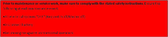
Inspection of Hall Sensors for possible oil weep.
Field reports have shown that a very few of our valued customers have experienced a small oil weep from the Hall sensors on the alternator side of the engine. Extensive investigation showed us that, in rare circumstances, the O-ring on the sensor may not have seated as expected due to factors outside of our control (tolerance related). We have taken appropriate production and supply actions to resolve this, implemented immediately.
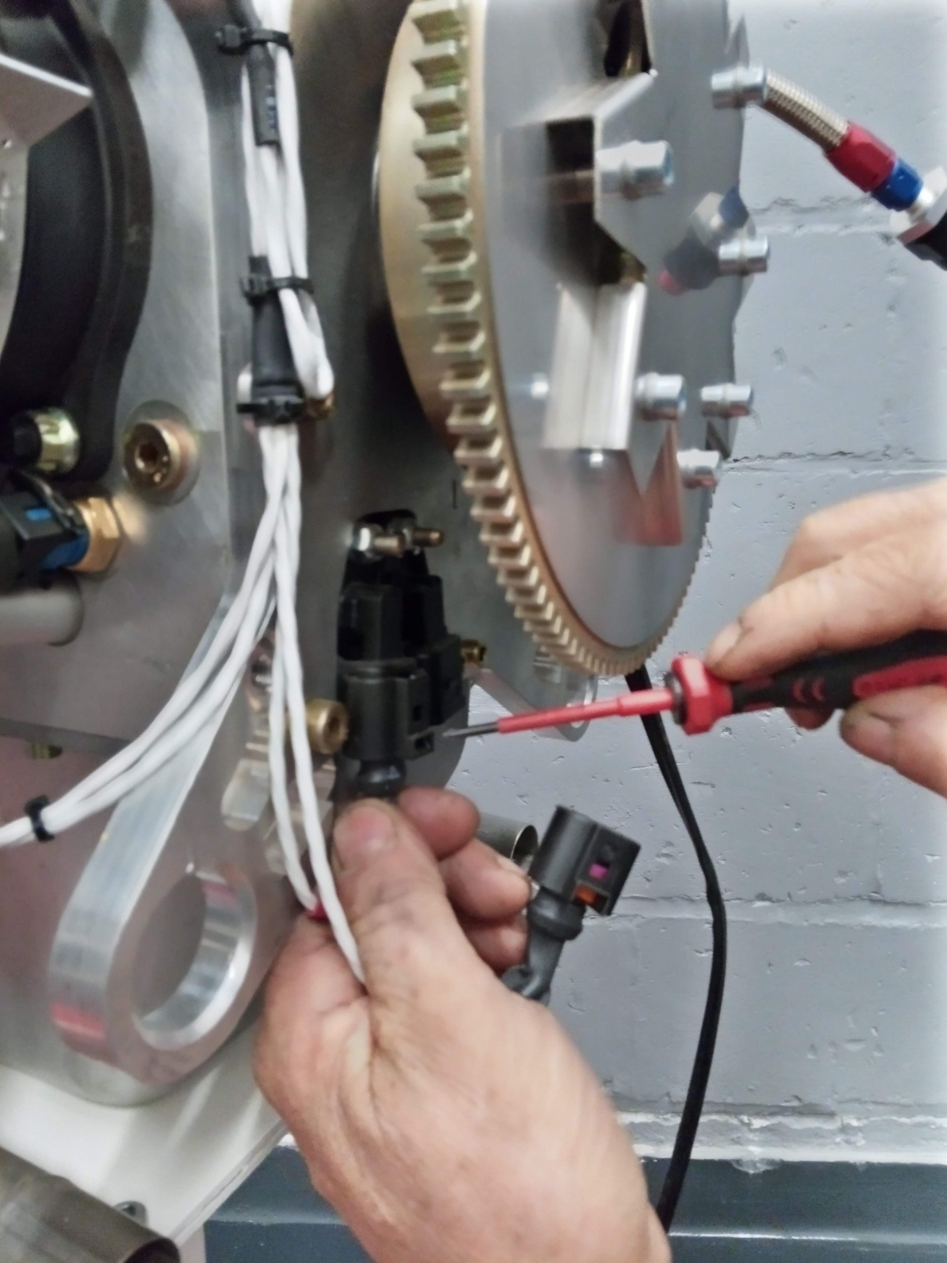
Consequently, we advise all operators to inspect these Hall sensors for oil weep at next service or within 25 flying hours.
NOTE: There is no need to replace the O-ring if there is no oil weep at the hall sensor.
However, should you notice an oil weep at a hall sensor, please replace the current O-ring with part number S1018116 O-ring to resolve the leak. Inspect again after engine run and first flight.
The new O-ring can be purchased through Wicks if you are in the USA or through your ULPower dealer.
So let’ take a look at the replacement procedure
Parts needed : S1018116 O-ring Viton 18.1×1.6 (2 for single ECUs and 4 for dual ECU)
Tools needed: wrench 10 mm
Suitable flat head screw driver
sealing silicone (e.g- Dirko Elring 030792 or similar)
For your reference you can find below a screenshot of page 24 in the IPC UL260i 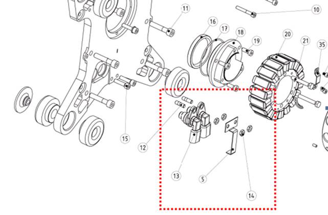
Guideline :
On tail dragger aircraft, consider levelling the aircraft before commencing work to avoid oil spills.
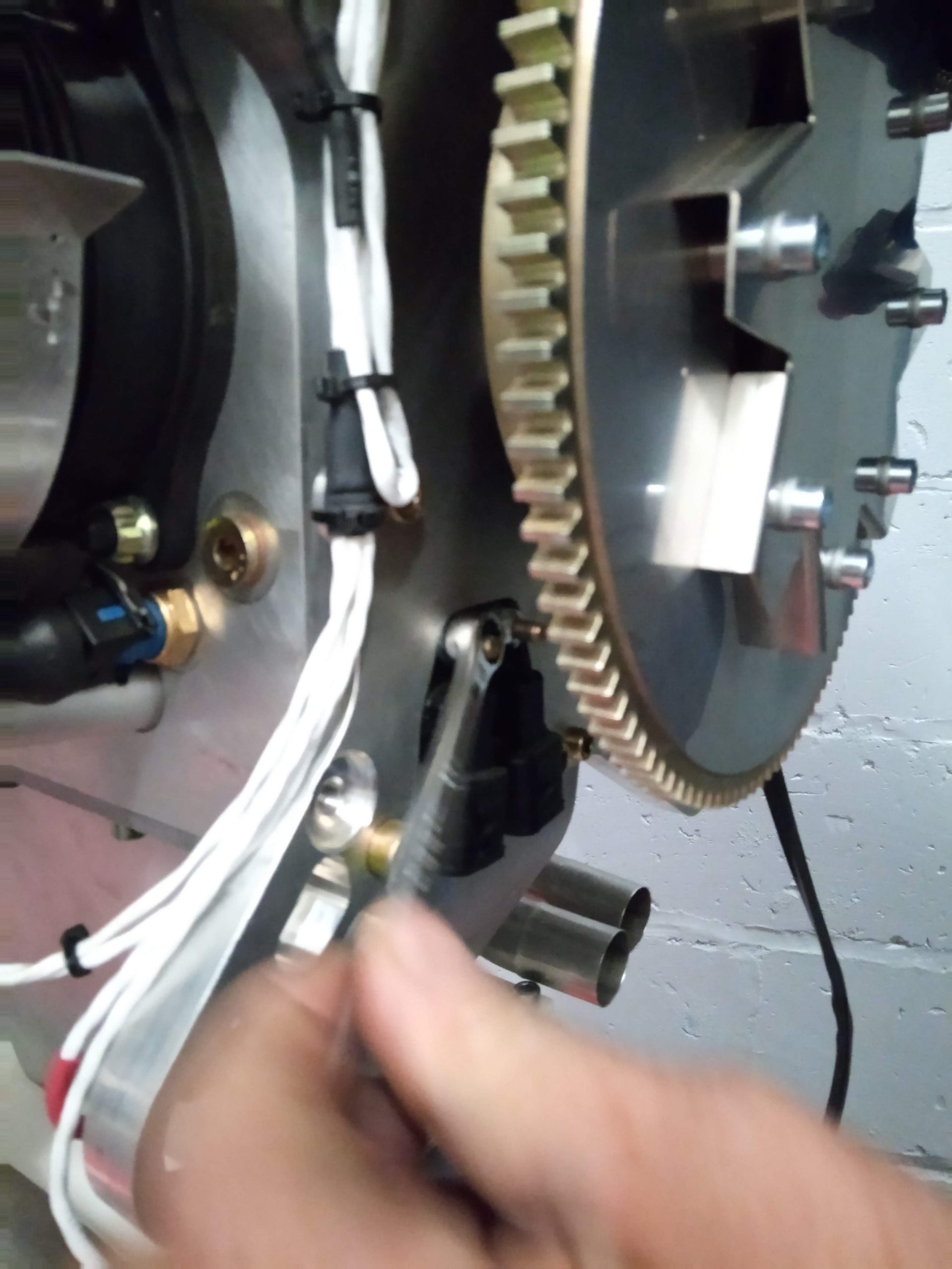
- Unscrew the 2 hexagon M6 nuts (IPC item 14) and remove the locking plate hall sensor (IPC item 5)
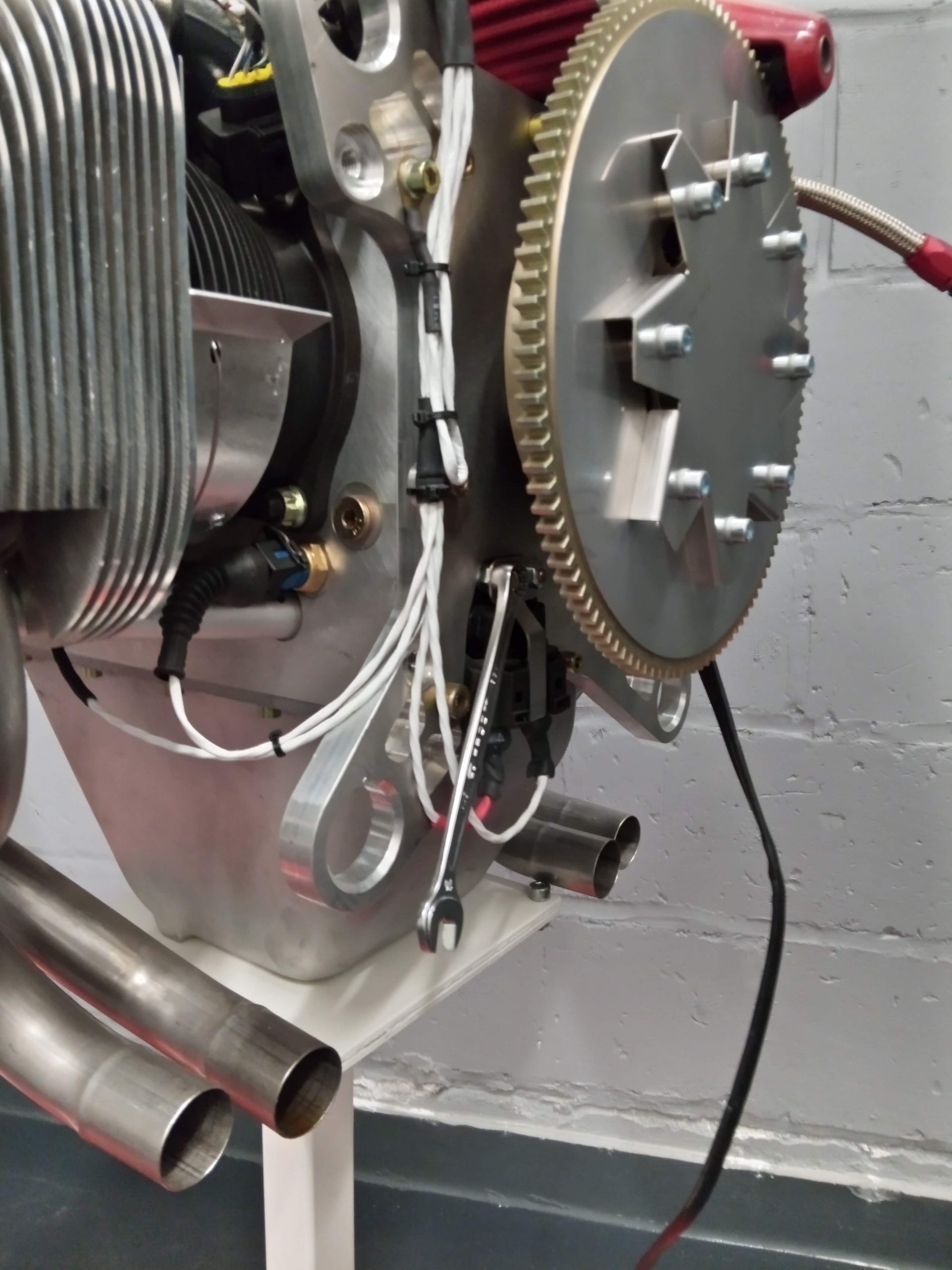
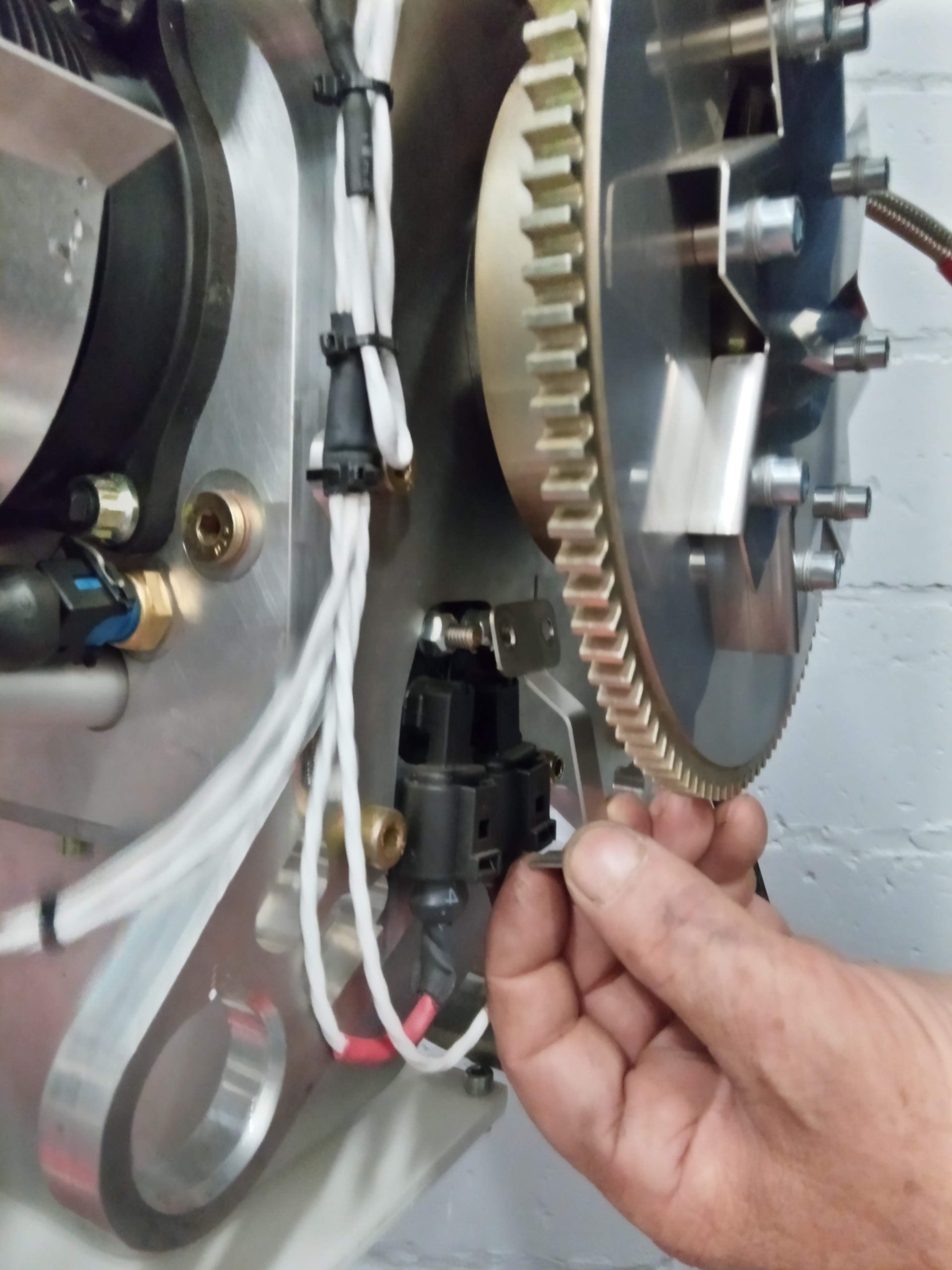
- Disconnect the 2 hall sensor connectors.
To do so, push the connector up, then push down the clips (use flat head screw driver). You are now able to remove the connector
- Unscrew the 2 hexagon M6 nuts (IPC item 14) which hold the hall sensors. Gently pull the sensor out of the backplate
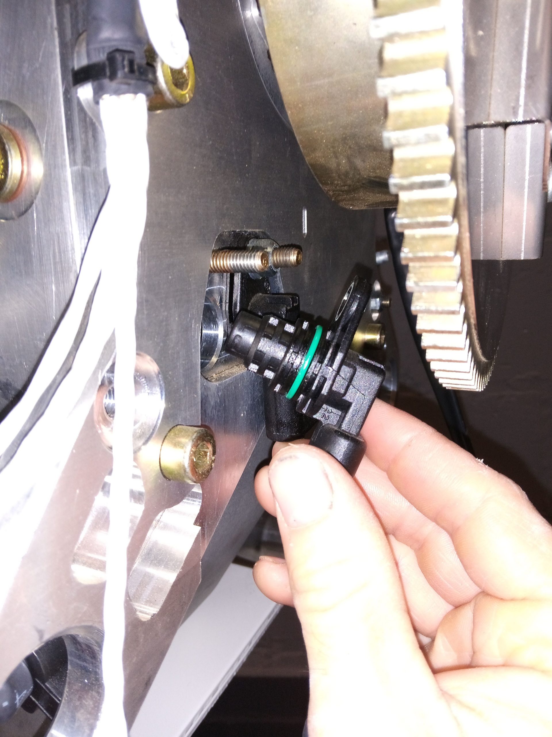

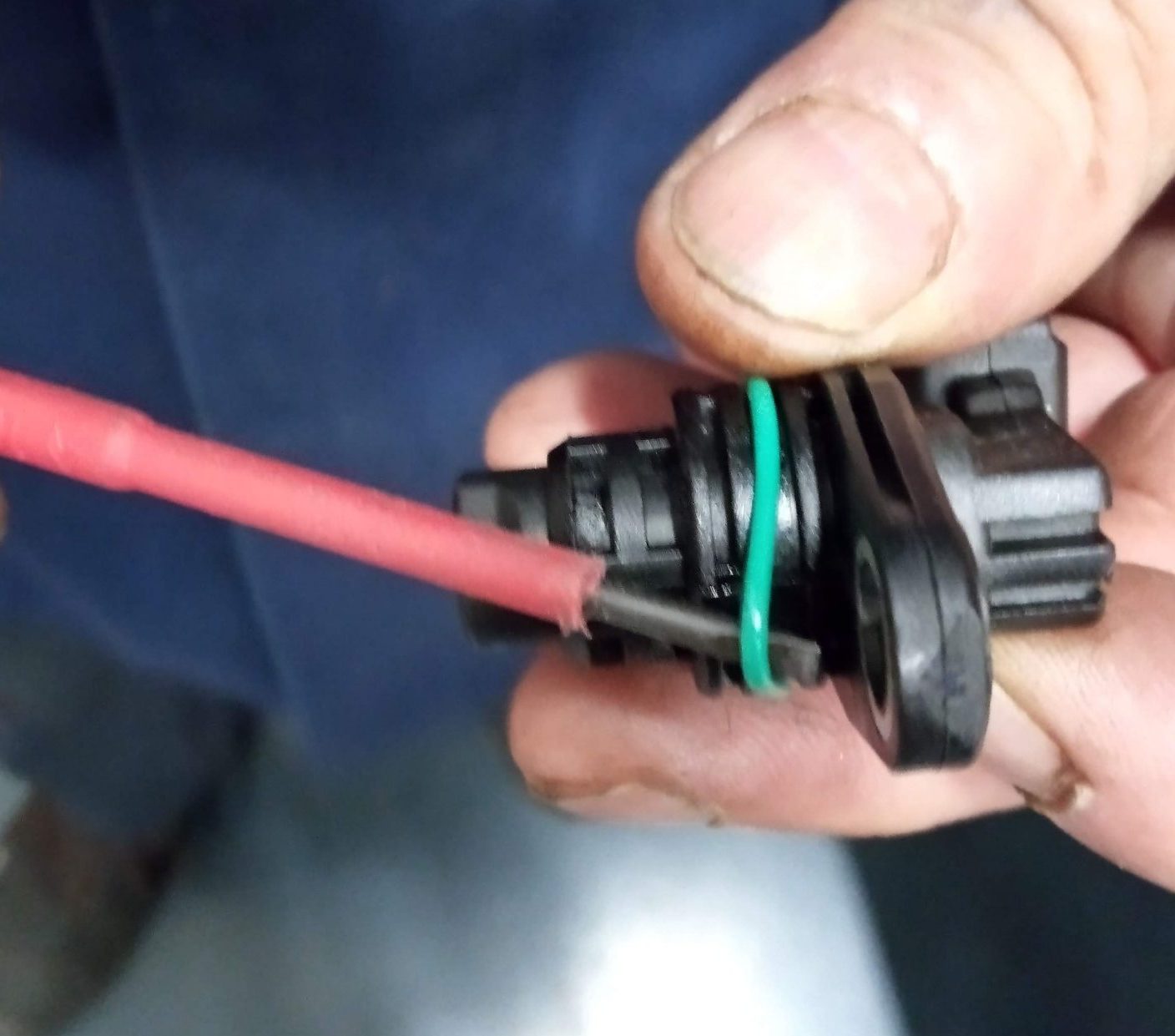
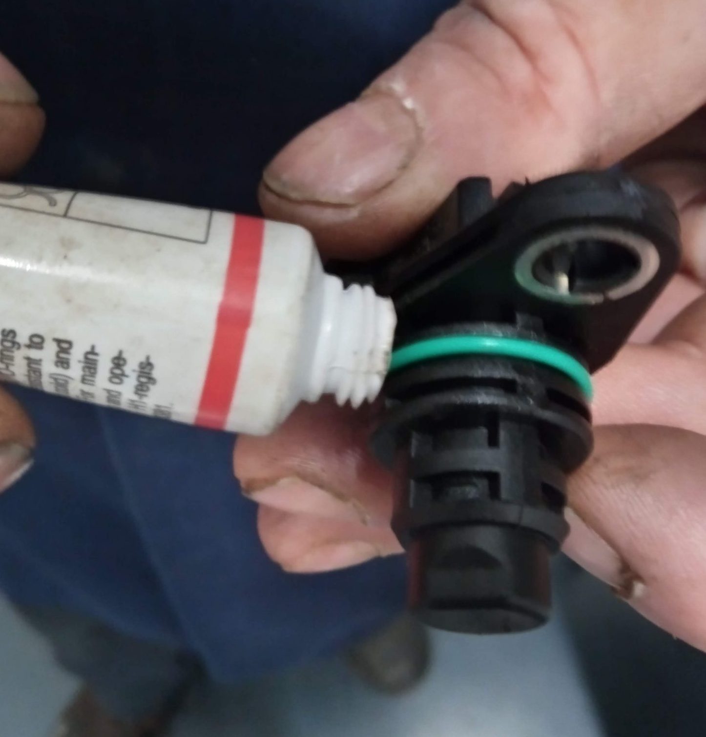
- Carefully remove the existing O-ring and install the new one (O-ring Viton S1018116)
- Add some sealing silicone on the O-rings before mounting
- Clean the sensor mounting hole in the backplate and glide in the sensor.
- Install the 2 hexagon M6 nuts (IPC item 14) and torque to 6Nm.
- Push in both connectors (ensure correct orientation of each sensor ).
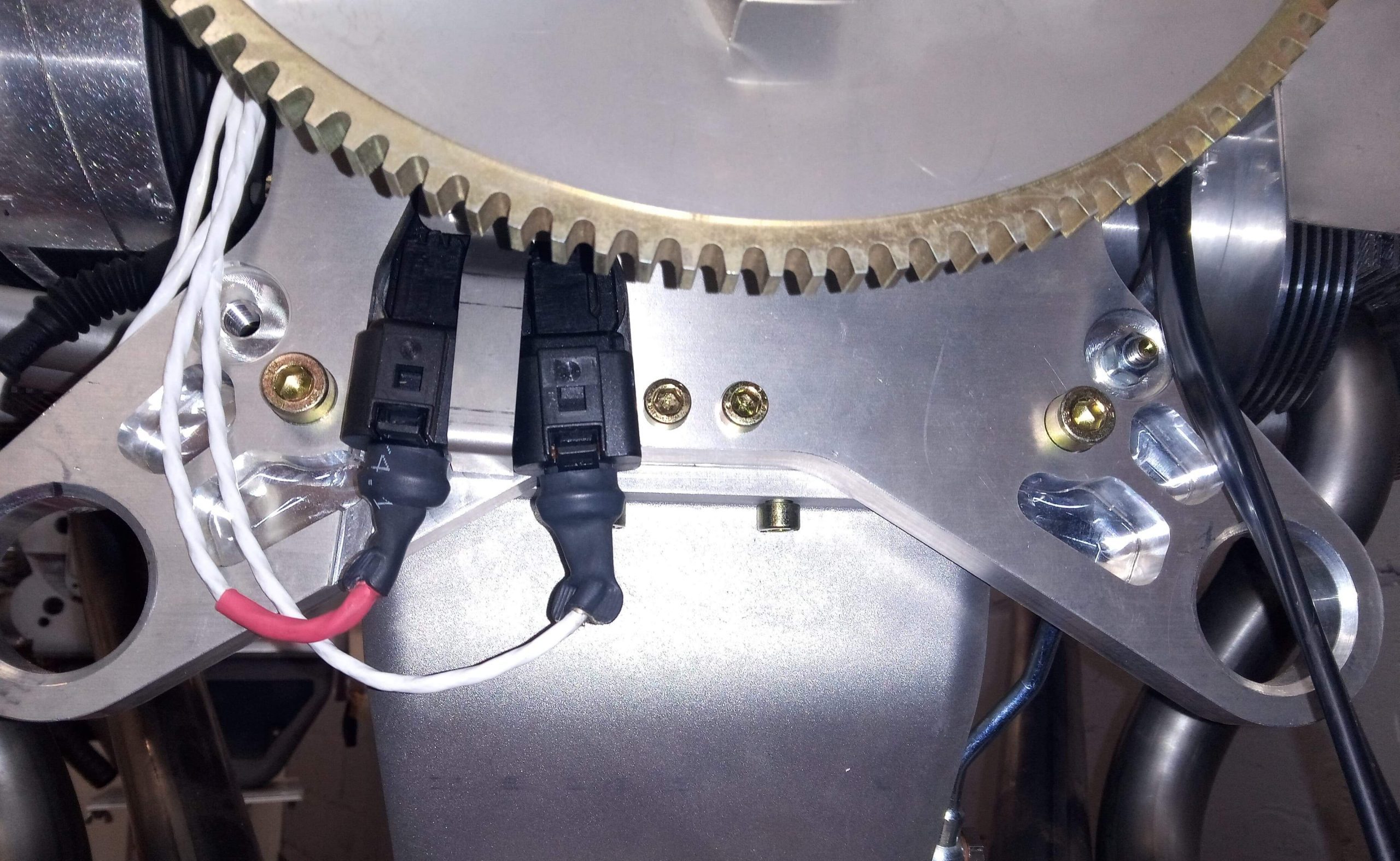
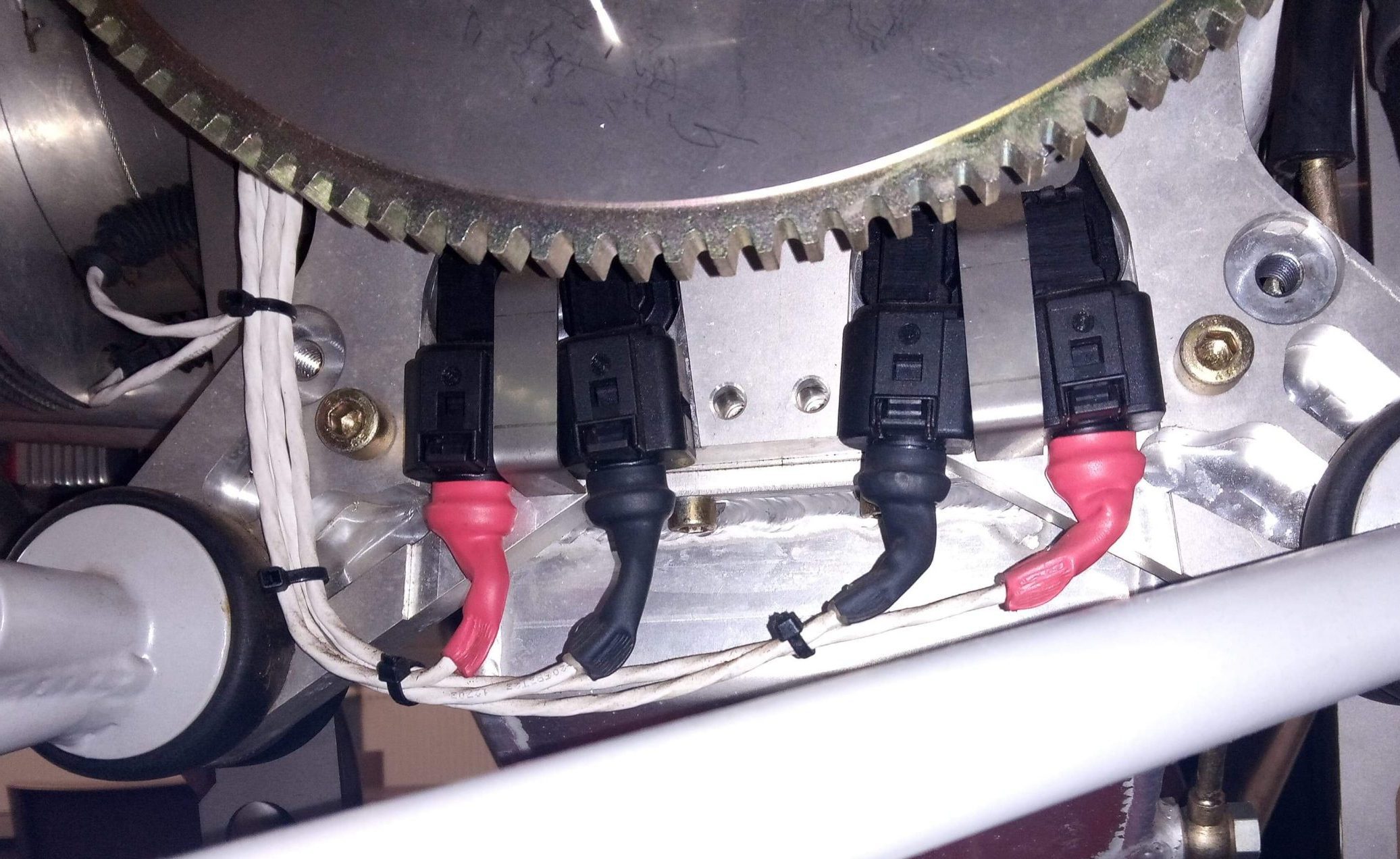
view on the sensors with single ecu sensors with dual ecu option

- Mount the locking plate (IPC item 5) and lock with 2 hexagon M6 nuts (IPC item 14). Torque the 2 nuts to 6Nm.
- In case of dual ECU, repeat these steps for the 2 other hall sensors (if necessary)
![]()