EGT sensors/senders
Installing EGT (Exhaust Gas Temperature) and CHT (Cylinder Head Temperature) sensor/senders onto your ULPower engine is not a difficult task, but it is important to get them installed correctly if the readings are to be useful to you as a pilot or engineer.
The ULPower Engine Control Unit (ECU) does NOT monitor the EGT nor the CHT temperatures , and does NOT use them in either MAP or error generations. This leaves the monitoring to the pilot, and allows for the use of either analogue gauges or a feed into a digital instrument of some kind (EFIS, or stand alone). EGT and CHT values are, apart from the use of power and pitch, in essence, outside of the control of the pilot once in normal flight. However, it is very much the responsibility of the builder to establish a good installation to ensure that the values remain in range during normal flight ops, which is then checked and tweaked as part of the test flight programme. During the initial testing of a new type/configuration of aircraft, there will be a number of flights needed to optimise the installation – this is where the EGT and CHT values provide an essential feedback with regards to the efficiency of the installation, giving the builder a chance to adjust baffles, cowlings, NACA ducts and perhaps tweak baffles/add bleed air/etc to establish that sweet spot for the ULPower installation to that airframe. Once the aircraft is ‘set-up’ and operating in limits, then the values become a health check to be monitored in flight, and if recorded to provide potential trend information over the life of the aircraft/engine.
The EGT limit is laid out in the Operations Manual (available from www.ulpower.com) and are the same values across the range of engines:-
EGT Max. 880°C (1616F) (red line)
EGT values will vary upon delivered power output, and it is most important that all EGT values are approximately equal – since each cylinder is being sent the same ‘mixture’ and should be generating approximately the same heat/energy output. Small variations are normal, due to other effects of cooling on the exhaust manifold itself.
The EGT sender is heated by the gasses coming from the combustion chamber… as they flow down the exhaust system they pass over the sender. The sender is generally a K type thermocouple that generates a small voltage based on the reaction of the different wires where they are joined at the sensing end. They can simply be wired to a suitable instrument. (If you prefer not to wire them yourself, the ULP Aux box option is available- ask your local agent for more inf0)
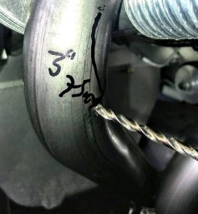
INSTALLATION: EGT senders should be installed at the correct distance from the ‘exhaust outlet’ on the cylinder head – and all senders should be within a few mm of the same distance, as prescribed in the installation manual – 75mm or 3″.
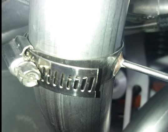
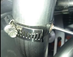
To install the clamp type, simply drill a small hole, to suit the EGT you are fitting, at the correct distance from the exhaust manifold ‘flange’, making sure that the orientation of the EGT sender and lead will not foul the cowling or other items,
Carefully insert the EGT
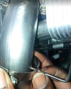
and tighten the clamp…

If the clamp is too long or risks fouling, it may be clipped back
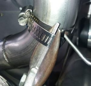
to give a neat installation
The ULPower Troubleshooting guide (available from www.ulpower.com) notes several factors that may affect EGT values, including
FAULTY SENSORS
INCORRECT SETTINGS ON INSTRUMENTS
NO SPARK OR NO FUEL INJECTION
BAD VALVE CLEARANCE SETTING
BAD CONTACT IN THE IGNITION WIRE CONNECTORS
INCORRECT TYPE OF FUEL
SUCKING AIR INTO THE FUEL LINES
INLET AIR TEMPERATURE TOO HIGH
If you haven’t downloaded the interactive guides for maintenance and troubleshooting, now is the time to do so!
If you are unsure about any aspect of your installation or troubleshooting, contact your local ULPower Dealer who will be ready to help you!