HT Cables…. Learning some tricks
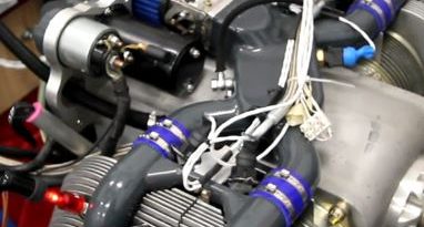
ULPower engines are designed to keep the electronics away from the ‘hot zone’ of the engine, and therefore the ignition coils are mounted on either the engine mount or firewall, away from the heat and vibration of the engine itself. This means that the exact HT (high tension or spark plug) cable length is not known until the engine and coils are mounted. Making up the cables is pretty straightforward, but there are some tricks to making them easier… Patrica from Metal Seagulls (UK), who is currently building a Zenair CH750 CRUZER with a UL350iS at the front, sent us the following.
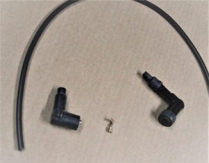
“When I am making up the HT leads for ULPower engines, I first cut a length of HT cable a bit longer than I think I will actually need, and layout the parts on my workspace…
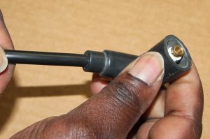
The cable, an ignition coil plug, a spark plug cap and the HT coil end copper terminal (all these parts come with the engine)
Toolwise, I layout my zip knife, soldering iron, solder, long nose pliers and my ‘third hand’ to hold the cable whilst I solder!
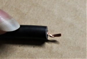
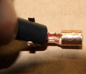
Using the zip knife, I cut carefully all around the insulation about 8 to 10 mm from the end of the cable, and then ‘gently twist and form’ the wire into a ‘small dog leg’ shape
 Next, I offer it up to the connector. If the wire is longer than the wire crimpable section by more than 0.5mm or so I trim it back until it looks roughly like this..
Now, I use the long nose pliers to crimp the wire into place.Crimping both sides to hold the wire in place… making sure that the wire does not extend into the ‘cone’ of the connector.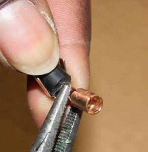
Carefully arranging the insulation into the insulation clamp zone (sometimes you need to open it a bit to get it into place first) I crimp the insulation into the clamps.
Until it looks a bit like this…. Do not worry if the insulation clamps are not ‘well closed’ onto the hard insulation at this time. BUT do check that the wire still comes about .5 mm past the wire crimps and definitely NOT into the ‘cone’.
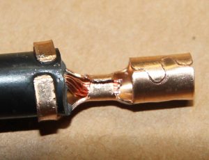
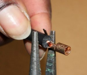
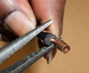
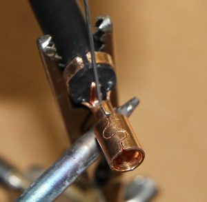
Using a pre-heated soldering iron I melt solder into the copper wire, making sure that it flows freely – but it must not enter the cone of the connector
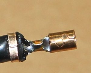
Carefully crimp the insulation a bit more now, whilst the insulation is still warm! It will enter nicely into the material giving a great grip and neat finish.
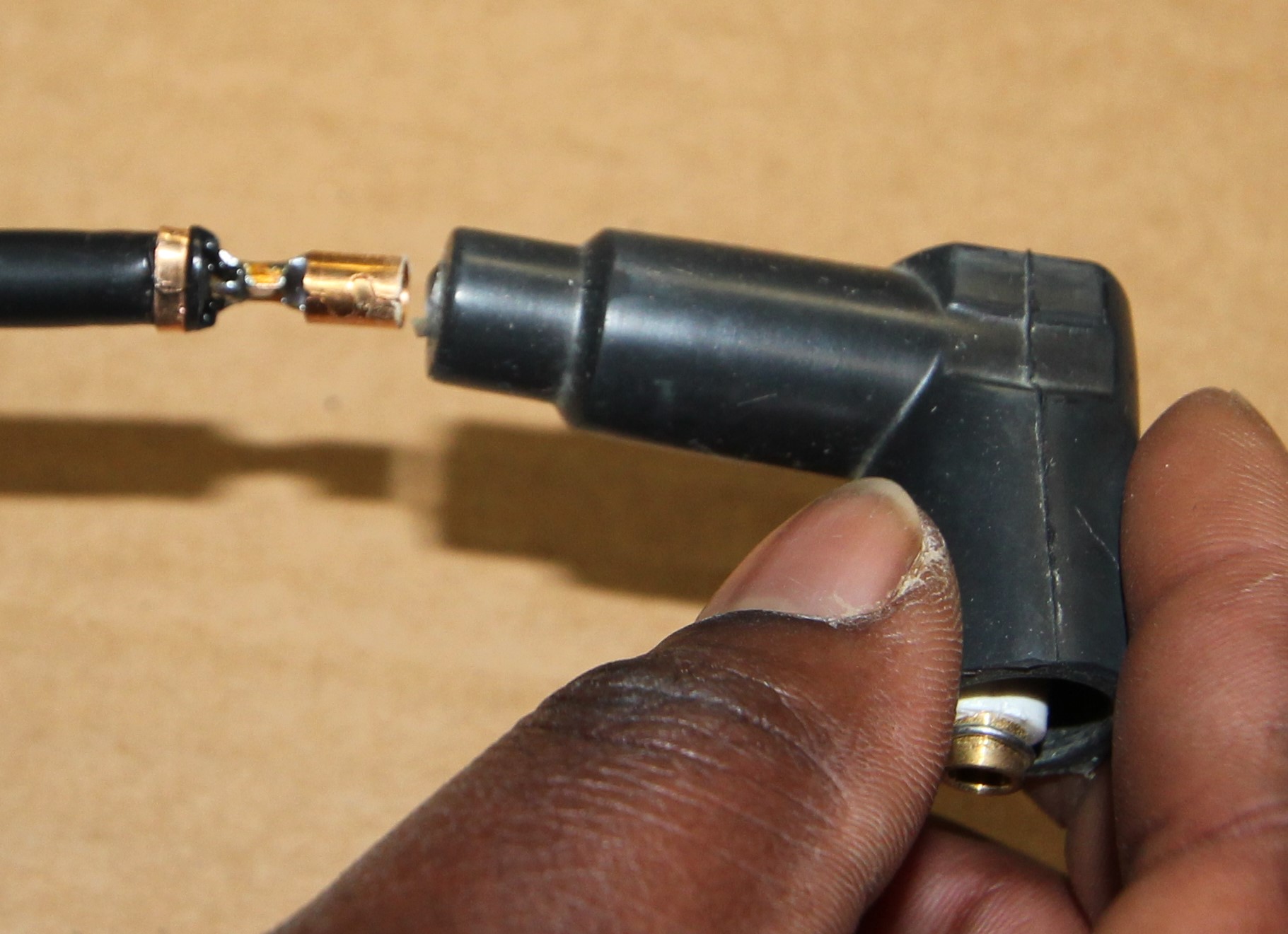
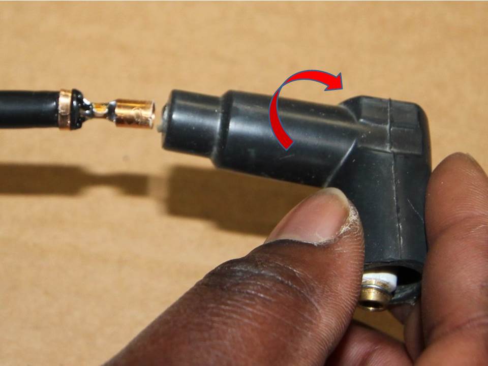
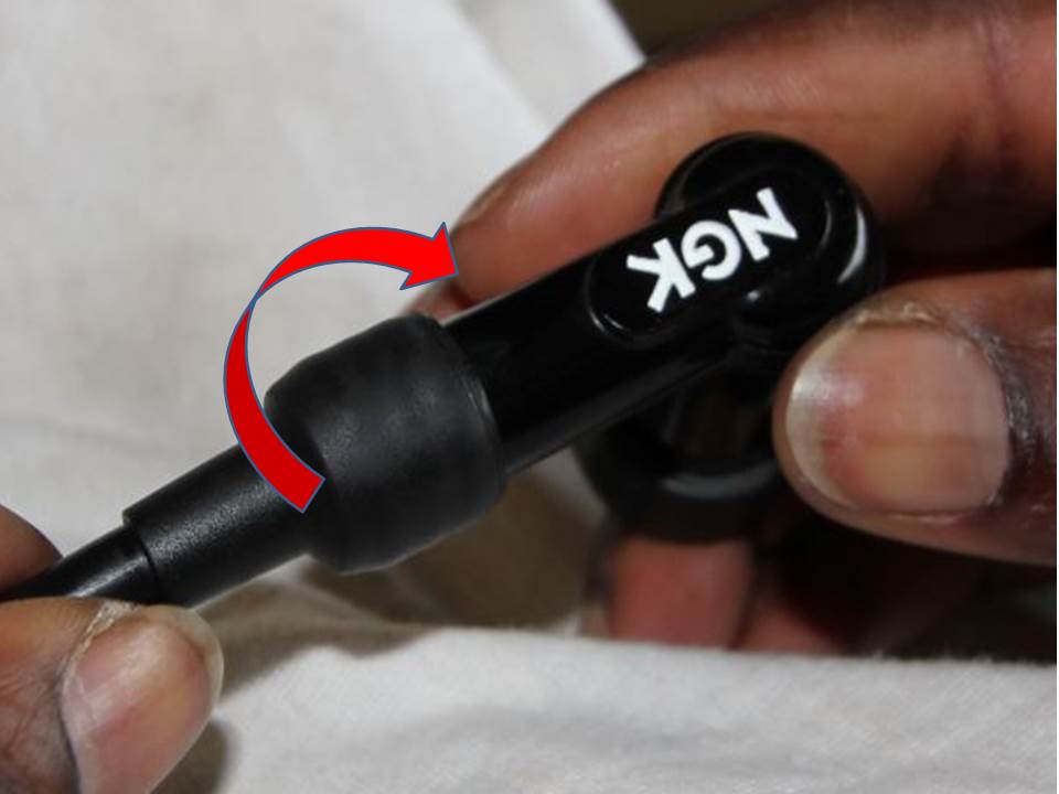
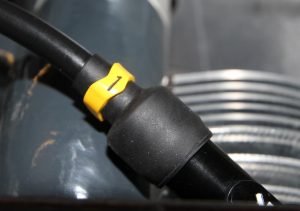
Insert the connector into the HT coil plug pusing until you feel a small ‘click’. Then rotate ‘to the right’ to tighten the connection, until it just stops turning (about 3 turns)
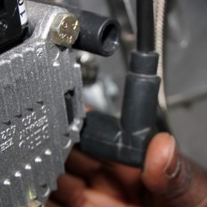
Now give it a gentle tug. The cable MUST NOT pull out. If it does, try to insert it again, and if it still wont work, cut off the copper terminal and start again (usually it is because wire or solder went too far towards the cone)! If it is holding well, take the cable and plug it into the ignition coil at the relevant position for the cable you are making (in this case for cylinder one, right)… Push the HT plug into position until you feel it click.
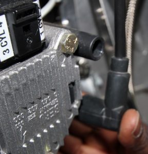
Firm pressure with your thumb will confirm it has made correct contact. Check that it does not pull off easily.
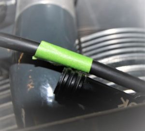
Pass the other end of the wire through the baffle grommet and lay it alongside the spark plug cap, located on the spark plug, it is destined to be terminated with. You may use a coloured masking tape to mark off the desired cut point (it is easier to see than a pen mark) – which should be around the end of the three rings on the spark plug cap.
Spray a little silicone lubricant onto the HT lead…
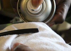
and slide the ‘rubber boot’ up the lead out of the way.
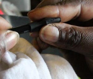
Now, insert the spark plug cap to the lead, as far as it will go without forcing it…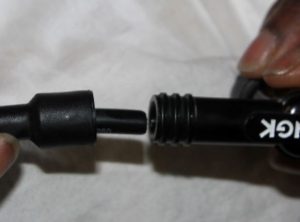
Applying a firm pressure, you can now screw the plug cap on until it stops ‘screwing in’ any more then slide the rubber boot over the end of the spark plug to prevent moisture and dirt entering the spark plug.
Try to pull the plug cap off the lead… and if it does not pull off …. it can be put onto the spark plug… If it does, you may need to trim the cable back 10 – 15mm and try again. DO NOT MAKE THE CABLE TOO SHORT, it must have some slack in it.
Just seven more to make up on my UL350iS (or eleven more if it was on a UL520iS!)
For those who want to go a bit further, you can slide a cylinder identifier (you can find them on e-bay) onto the lead before you add the rubber boot…”
If you are not sure about how to make up your HT leads, ask your ULPower dealer (they often run installation courses or can talk you through the procedure) or a person familiar with making up HT Cables….
If you have some tips to share with us at ULPower.news, just send them to us at editor@ulpower.news