Rectifier/Regulator – Hints n Tips!
Before we give you some hints & tips about the rectifier/regulator installation, lets take a look at a simplified explanation of its function.
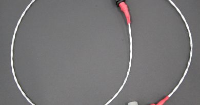
The alternator / generator produces 3 phase AC electricity.
The regulator/rectifier converts the 3phase AC into a unstable DC between 12 and 15.5 V. The battery buffers this unstable DC output and converts it into a stable DC output. It is very important to never disconnect the regulator from the battery when the engine is running. Doing so would destroy the regulator. (If there is communication between battery and regulator, that would mean that the regulator keeps working which can result in overheating ). When the maximum voltage is reached, the rectifier/regulator will stop feeding DC into the battery. Depending on the type of battery, the rectifier will shut down the DC output to the battery when the voltage level is between 14 and 15.5 V.
The ECU needs a stable DC output . If the battery dies, or there is an open contact inside, the buffering characteristics from the battery perish . To avoid that the regulator is in direct contact with the ECU, and thus supplying unstable electricity, we strongly recommend to install a genuine ULP capacitor (this capacitor is able to cover for the big amount of amps coming from the alternator/regulator) parallel on the battery.
How is this done on the ULPower….? Well, let’s look at the manual…and see if we can give you some extra tips
According to the manual, following guidelines must be followed :
Install the RR
- Away from vibrations (the firewall is probably the ‘least vibration’ zone).
- Away from HEAT (the firewall is often the furthest point from heat)
- With heat transfer paste/or a pad behind the RR (to assist in heat transfer). (NB if the firewall is not metal you may want to mount it on a small plate to assist with heat dissipation.) – and at times the mating point between the two surfaces is not perfectly flat, allowing the thermal paste to improve transfer.
- Ensure cooling air is vented over the fins.
- Make sure the connector is horizontal or ‘at the bottom’ to avoid moisture entering the connector
- Make sure that the connectors and wires are properly crimped, inserted and connected AND routed away from sources of heat and mechanical damage.
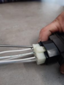
True to the ULPower philosophy “ easy to install “ and the “almost ready to fly” concept, all ULPower engines are supplied with a with prewired connector that is preinstalled in rectifier/regulator.
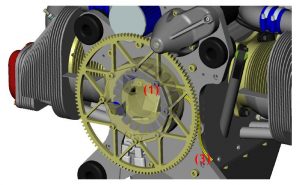
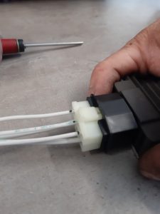
If , for some reason, you need to disconnect the prewired connector from the regulator, there is a simple trick to make sure your connectors to the regulator are ‘home’. Before disconnecting make a little black mark on the wires at the ENTRY to the connectors
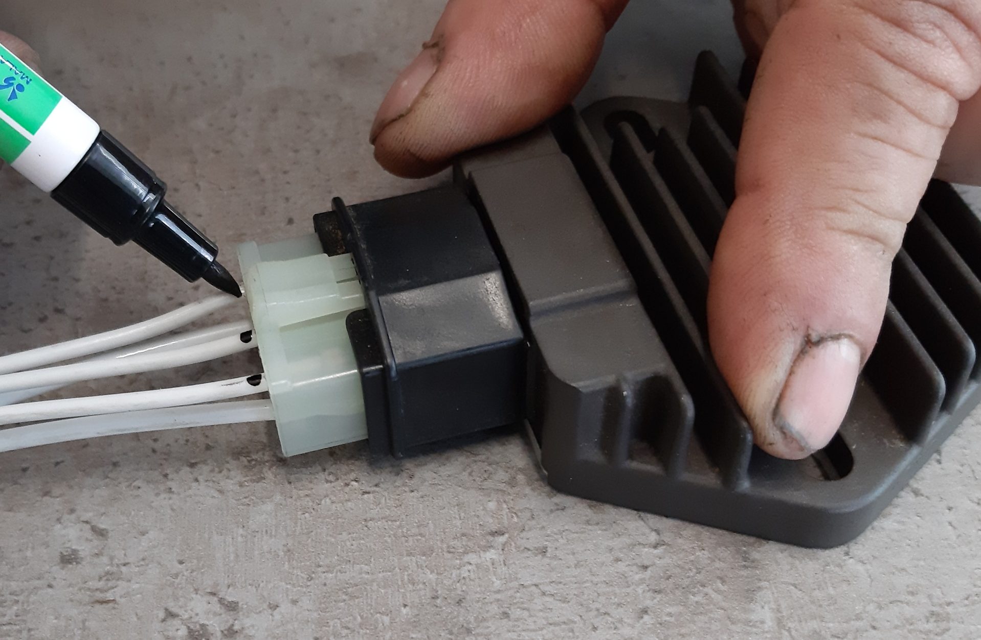
Now, when you reconnect the connector to the Rectifier body, you can see if the ‘connectors’ have gone in correctly… because the lines will fall out of position.. should that happen, simply use a small screwdriver to CAREFULLY align the connector (make sure you do not damage any wires nor the housing) and
When it is all correct, you can move on to the mounting….
MOUNTING THE RECTIFIER/REGULATOR sounds nice and easy, but we do need to take into account the points raised above…Below you can find an example of a “best practice” installation. Of course not all installations are the same and it is up to the builder to decide how and where he will install the RR. Other ways are possible as long as the general idea of the IM is followed. Another example of bringing cool air to the RR can be found in our manual..
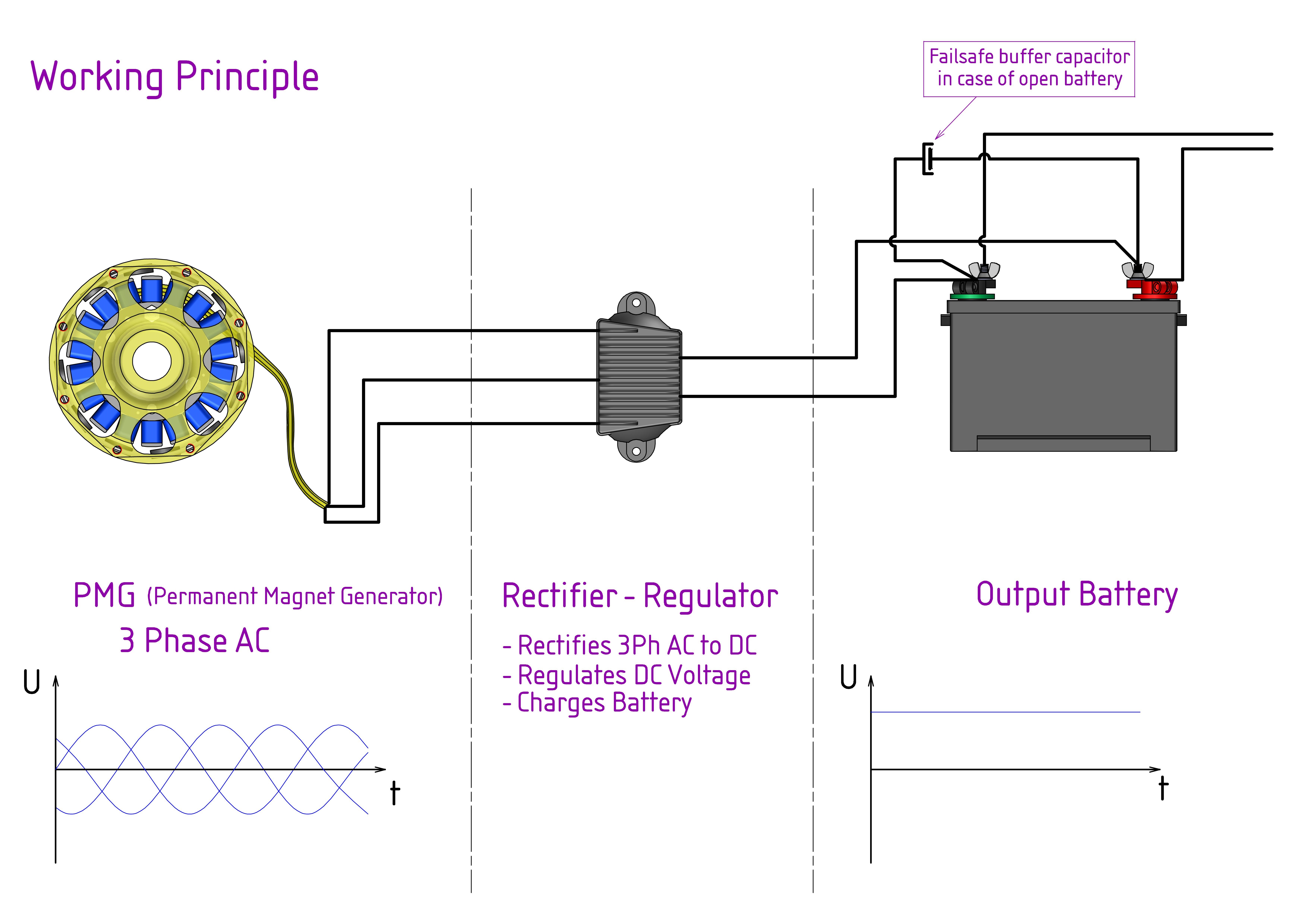
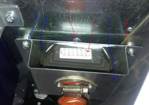
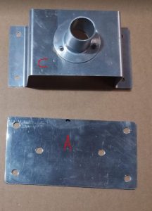
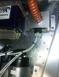
For this installation, we are going to use the firewall… BUT there is a problem. Where we want to mount it there is a rivet (1) and also there is a stiffener (2) – making it impossible to get a ‘clean seat’ for the rectifier. So, we are going to mount it on a heat sink plate of .032″ aluminium (A) – we could use thicker or thinner, but it must be sturdy enough to support the rectifier. We will ‘offstand’ the plate from the firewall using washers (B), and the mount a top hat section (C) on top with a blast of air, bled from the air plenums over the cylinder (1″ hose is enough). As you will see in the pictures, we have used a thermal transfer paste (the same as used on spark plug threads or computer processors/cooling fans) and also ensured that the connector is ‘down’ and away from heat, moisture and vibration.
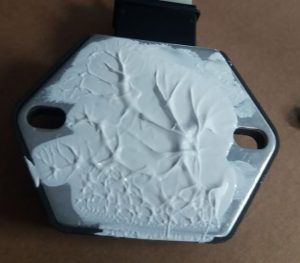
In order to monitor the temperatures that the regulator may reach we add a thermal tape to the top. This lets us know the MAX temp the regulator reaches as the ‘indicator’ will turn black as soon as the reference temp is reached. You will note that the capacitor (bottom of the picture below) also has a temp tape on the capacitor holder – which is another ‘good practice’ aspect of your installation.
The two ‘rear’ wires are for the airframe, and the three ‘front’ wires go to the engine alternator/generator. The ‘red shrink wrap’ tagged ‘rear’ wire should be connected as follows:
- If the battery terminal is within one metre (about a yard) of the rectifier, you can connect to the that location.
- If the battery is more than a meter away, it is better to route the wire to the ‘+ve’ on the starter on the engine. (which has a large section wire to the battery, of course!)
- If a battery post is in use, which has a large section wire to the battery AND is less than one metre away, and more suitable to connect to than the battery +ve and starter +ve
Now, all that is left is to crimp the connectors to join the wires between the rectifier and the regulator. Make sure that each connector is well crimped and inserted correctly with a firm ‘click’ into the relevant male/female.
.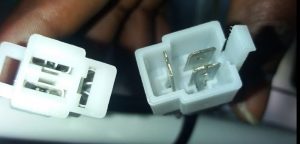
Then, when connecting the two you must ensure that the ‘latch’ is caught on the housing too!
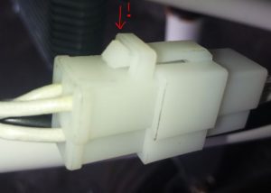
Take your time to make the connectors up properly and ensure good crimping and seating. We have seen several of these poorly connected in the field with evidence of ‘browning’ from overheating. If necessary it is possible to replace this connector with ‘cable joints’ BUT it will create its own issues – so where possible stick to the connector and connect it properly!
If you have any tips & tricks about your ULPower installation that you would like to share with other builders, feel free to send your text to editor@ulpower.news