What is so special about the ULP ECU – and how does the Dual ECU system work?
The ULPower.news team decided it was time to find out more about the ULPower ECU – the brain that controls the engine!
As you may have read in previous articles, the vast majority of the ULPower engine components are manufactured in-house or within the ownership group of companies. The ECU is no different!
The compact, aluminium bodied, ECU was developed by the ULP engineering team and has been thoroughly tested, passing the rigorous RTCA/DO-160D for EMC(electromagnetic compatibility) and vibrations.
OK… so what does that mean? Well, it means that the ECU is really tough….it can handle vibrations, lightning, magnetic interference, etc. without any influence on the functionality of the electronics.
With close to 15 years’ experience ,this ECU has an excellent operational record.
How a little red box makes a pilot’s life so much easier.
The ECU controls the mixture and timing from start-up to shut-down. As a result, in the cockpit, there is no choke, no primer, no carb heat, and no mixture; just a single lever – the throttle. Often referred to as a FADEC (Fully Automated Digital Engine Control).
The FADEC system automatically sets the fuel mixture and ignition timing (multiple times per second!). It will even fine tune the fuel flow to compensate for changes in barometric pressure as well as inlet air temperature in the inlet manifold/airbox. This brings a definite bonus on cold and “hot” starts, as any ULPower owner will tell you!
With timing corrections to avoid detonation and a built-in rev-limiter (3,300rpm on most engines) the ECU not only ensures the most efficient power to fuel consumption at any given operating condition, but it also brings extra safety.
The ECU contains a table of data, referred to as a ‘3-dimensional fuel map’. The map itself contains the mixture and timing control for operations up to 18.000 ft, based on data received from five different senders
- CPS -Crank Shaft Position Sensor/RPM ,
- TPS – Throttle Position Sensor
- OTS – Oil Temperature Sensor
- ATS – Airbox/inlet manifold Air temperature sensor
- APS – Air Pressure Sensor (air pressure is taken near the air filter and linked via a hose to the ECU where the sensor is housed).
So, how is the data used?
| Throttle Position | Used to know %age power setting and also to know if ‘accelerating’ |
| Ambient Air Pressure and AirBox(manifold) temperature | By knowing the ambient air pressure and temperature it is possible to calculate the air density to determine the correct amount of fuel to add for the ‘right mixture’. |
| Oil Temperature | This lets the ECU know whether it is a hot start or a cold start and to manage the engine accordingly with fuel to air ratio (rich or lean) and advance/retard. Based on this input, the ECU can automatically adjust the mixture to ensure easy starting and smooth running until the engine is at operating temperature. |
| Crankshaft position | By knowing the crankshaft position, the RPM and position of each cylinder’s piston and valves is known. This allows the ECU to calculate when to trigger the spark plugs/advance/retard the engine for smooth running. |
| Rpm | Rpm and TPS together determine at what point on the fuel map the ECU should work from. |
If one of the above-mentioned sensors fails or becomes disconnected, the engine will continue to run, but not as efficiently as it will be using ‘default values’. The only sensor that is critical to continued operation of any ECU controlled engine is the crankshaft position sensor.
Should a sensor come disconnected an error message is issued by the ECU in the data stream to the EFIS and the UL warning light will come on. As soon as the error is cleared, the warning light will go off and the error message removed from the data transmission to the EFIS. If the warning is intermittent, it may indicate a poor or loose connection or a break in a wire. Much as the engine will continue to run in error mode, it is strongly recommended to establish and maintain a ‘clear glide’ flight path with emergency landing sites in range, and to land as soon as possible, as is standard practice with any aircraft engine which may develop a fault in flight. It is worth noting that if the ECU’s goes into error mode you may find an increase in fuel burn. The advantage with the ULPower engine, is that (EFIS error message reading permitting) you can read WHAT the error is, providing increased pilot awareness of the situation.
The diagram below gives helps us to understand the data provided through the ECU to the EFIS.
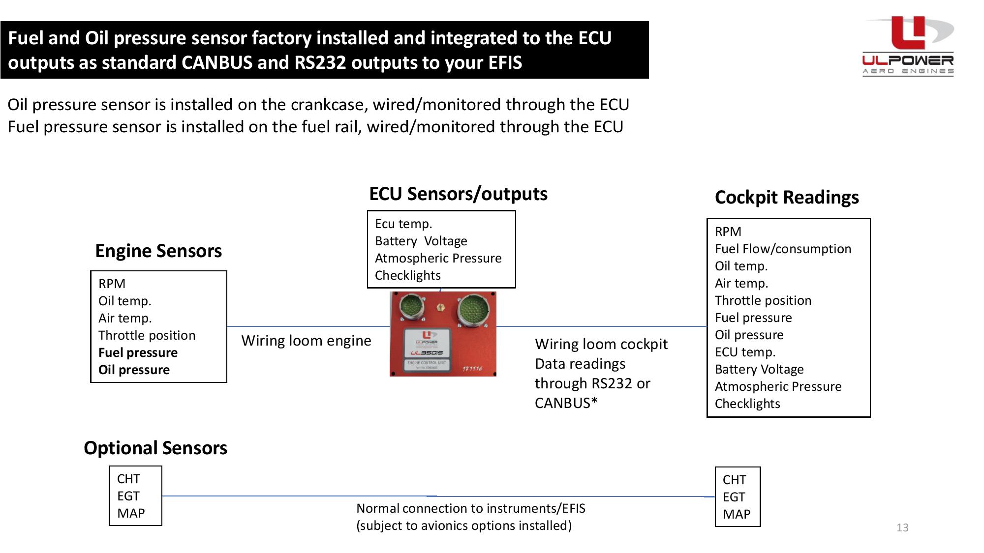
By connecting the ULPower EFIS connection cable with your EFIS connection cable, all data from the ECU is sent to your avionics device. Just plug it into the related sockets and you’re all set.
ULPower really does like to make installation simple!
What about Dual ECUs?
For mission critical applications or by personal choice you can run the ULPower Aero Engine with TWO ECUs – at the same time. This is called a Dual ECU installation, and offers ‘ECU redundancy’.
On a dual ECU installation, there are two of each sensor and two ECUs. The two ECUs are both “on” but work in ‘Active Standby’. The advantage of the active standby system is that one ECU automatically takes over the entire engine management in the highly unlikely event of the other ECU failing. (e.g if the power to ECU 1 drops below 12V, ECU 2 will automatically take over) and thus ensuring a seamless running engine.
When choosing the dual ecu option, each ECU controls one fuel pump and one coil. As flying on both pumps is only allowed for 10 minutes (during take-off and landing) it is important to ensure a good electrical installation . The ULPower manuals contain a wiring diagram which allows you to easily switch over fuel pumps.
You should also note that the fuel flow figures from both ECUs are NOT cumulative, but only the ‘larger flow’ value should be used. You may want to run your EFIS systems so that EACH EFIS is calculating remaining fuel, and then in the event of an ECU error occurring, consider the ‘highest consumption’ as your actual consumption.
Flying and operating the aircraft is no different with two ECUs to when there is one ECU. You still have the one throttle cable (but its position is monitored by TWO Throttle Position Sensors).
When flying with both ECUs ON all the time,it is very important to remember that your electrical power consumption will be higher , and those with 30A alternators may want to consider the 50A alternator option.
Dual ECU installations by their design have a lot more data outputs – two throttle position, two airbox temperatures, two ambient air pressure, two oil temperatures, two RPM, two ECU temperatures, two ECU volts, two fuel pressures, two oil pressures , etc. However, there will be only one set of EGT/CHT figures. Consideration of EFIS options is important when considering dual ECU options.
WHAT IF YOU WANT TO MAKE IT MORE COMPLEX?
If you want to deviate from the recommended wiring scheme, please make sure you have a suitable electrical background, and seek independent checking of your proposed installation, as this makes the installation extremely complex. Note ULPower does not offer this service, and only recommends the standard wiring. By making the system more complex you may create extra potential points of failure and must be very sure of your system. Remember that the extra security you may have hoped to achieve might be undone in part by a wrong electrical connection or added pilot workload.
The ULPower Dual ECU option is available across the entire ULPower range of aero engines and offers the most robust back up system possible for this class of engine.
To find out more, speak to your local ULPower dealer see www.ulpower.com